
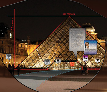
 Artist’s interpretation of augmented-reality view, applied to the Pyramide du Louvre, Paris, France. [Phil Saunders/spacechannel.org]
Augmented-reality (AR) technology enhances the physical world with real-time overlays of sound, video, graphics and navigation data. AR devices are already being used in a wide range of fields—from medicine, defense and manufacturing to information access and entertainment—and in a wide range of platforms—from hand-held, eyeglass and head-mounted displays (HMDs) to “smart” contact lenses. The research firm MarketsandMarkets has projected global demand for AR technology at nearly US$660 million by 2018, with the possibility of widespread use in education applications as early as this year.
Driving growth for AR are advances in hardware and broadband Internet connectivity. But this potentially world-changing and lucrative technology has at least one obstacle to overcome before becoming a commercial success—visual fatigue. A big problem for short-distance viewing in particular, AR-related eye fatigue happens owing to disconnects, or mismatches, between the 2-D image on the display screen and the 3-D real-world view just beyond the device. The problem of visual fatigue may be one reason that the Wall Street Journal has described AR as stagnating in a “new-tech purgatory.”
Fortunately, two strands of optical technology—integral imaging and freeform optics—could provide solutions to the eye fatigue puzzle in AR. We have recently combined these techniques into a prototype HMD that superimposes a 3-D image onto the user’s real-world view, thereby eliminating the visual mismatch that has plagued fixed 2-D screen devices. Fixing AR’s visual-fatigue problem through technologies such as these could ultimately result in lightweight, compact and high-performance devices that redefine the boundaries between the physical and digital world.
The roots of the eye fatigue problem
One of the biggest challenges in designing a comfortable optical see-through head-mounted display (OST-HMD) is eliminating accommodation-convergence cue discrepancy—a key factor contributing to eye fatigue. The “discrepancy” refers to conflicting depth perception cues caused by the user’s eyes moving back and forth between the fixed 2-D screen and the real-world scene beyond the projection. Users can experience three types of conflicting depth perception cues when wearing an OST-HMD with a fixed 2-D image plane:
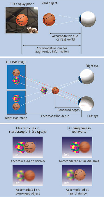 Visual cue conflicts in OST-HMDs: (Top) Accommodation cues are mismatched between display and real-world scenes in a monocular, non-stereoscopic display. (Center) Accommodation-convergence cues are mismatched in a binocular, stereoscopic 3-D display. (Bottom) Retinal image-blurring cues are mismatched between simulated 3-D and real-world scenes. [Phil Saunders/Adapted from H. Hua and B. Javidi. Opt. Express 22, 13484 (2014)]
2-D image/3-D real world: monocular display. In the first scenario, the user experiences conflicting cues between the 3-D real-world image and the 2-D projected image in a flat monocular display. The eye is cued to accommodate at the 2-D image plane, while the same eye is concurrently cued to accommodate and converge at the depth of a real 3-D object onto which the 2-D image is overlaid. The distance gap between the display plane and real-world objects is often beyond what the human eye can accommodate.
2-D image/3-D virtual world: binocular display. In the second scenario, the mismatch of accommodation and convergence cues is between the 2-D image plane and the 3-D virtual world graphically rendered in a binocular stereoscopic display. When viewing the augmented 3-D scene, the eye is cued to accommodate at the 2-D display surfaces to bring the digital information in focus, but at the same time, the eye is forced to converge at the depth dictated by the binocular disparity (i.e., parallax) to fuse the stereoscopic pair. (The difference in perceived position of an object viewed with one eye compared to the other is called parallax and helps with depth perception.)
Retinal image blur mismatch. The third conflicting-cue scenario is the mismatch of retinal image-blurring cues between augmented 3-D and real-world scenes. Synthetic objects rendered via stereoscopic images, regardless of their distance from the user, are seen clearly if the viewer focuses on the image plane, but are seen blurred if the user focuses at distances other than the image plane. The retinal image blur of the augmented scene does not vary with distance from an eye fixation point to other points at different depths in the simulated scene.
These visual cue conflicts can cause problems familiar with anyone who has used a stereoscopic display: distorted depth perception, diplopic vision, visual discomfort and fatigue, and degradation in oculomotor response. Developing technologies less vulnerable to visual fatigue is therefore crucial for applications that require users to wear AR displays for long periods.
Fundamentally, overcoming all three types of accommodation-convergence discrepancies requires overcoming the problem of integrating a 3-D display with a real or implied fixed 2-D image plane. That is, we need to find a way to display 3-D AR scenes with correctly rendered focus cues for the intended distance correlated with the eye convergence depth. And, given the current market, we need to do it in an optical design as compelling as a pair of eyeglasses.
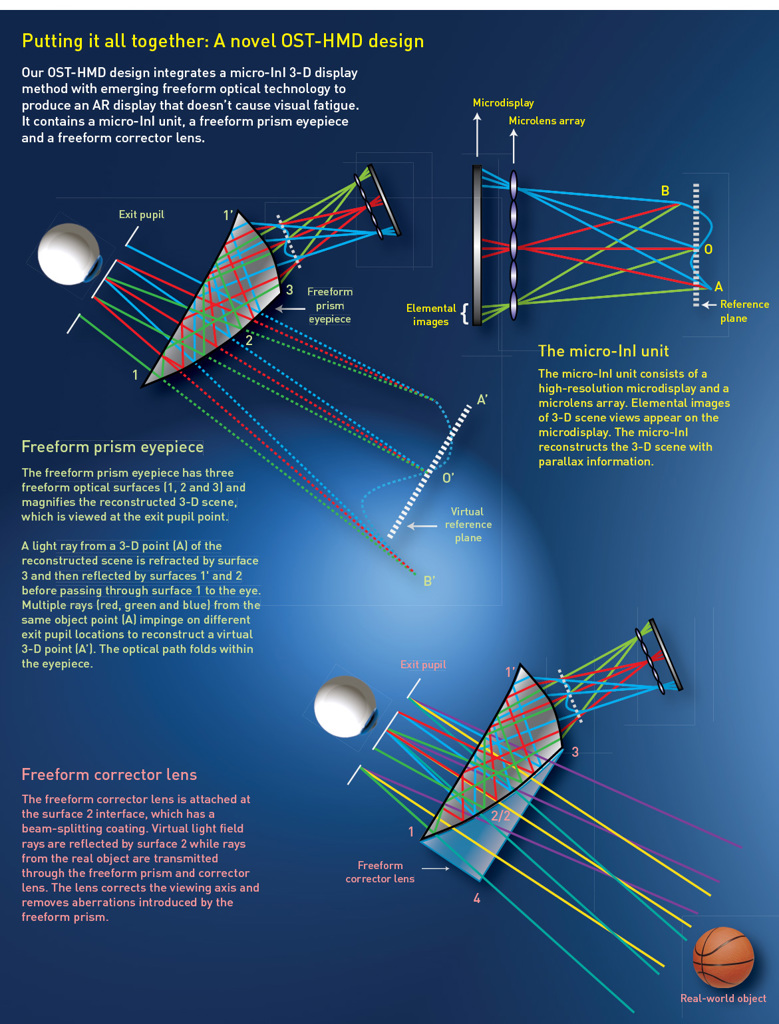
Our team has lately had some success in both requirements, by an approach that combines microscopic integral imaging (micro-InI) to create the 3-D scene, and emerging freeform optical eyepiece technology in a compact HMD.
Creating 3-D with micro-InI
Integral imaging, proposed by Nobel Laureate Gabriel Lippmann in 1908, is a passive multi-perspective imaging technique that can work with simple optical and optoelectronic components. The operating principle of integral imaging differs profoundly from that of holography, which requires coherent light and coherent interference to record 3-D information. Integral imaging can capture and display a full-color 3-D scene with incoherent or ambient light. And since it uses incoherent light, the images do not suffer from speckle degradation as holograms do.
During the capture stage, an InI device captures a large number of 2-D perspectives, or elemental images, of the 3-D scene. In principle, the capture is similar to that of an insect’s compound eye, pulling in a variety of 2-D images at slightly different angles of view. Then, during the InI 3-D display stage, the reverse happens: elemental images are displayed on a screen and projected through an array of tiny “lenslets” to reconstruct the 3-D scene.
The 3-D object is formed by the intersecting ray-cones arising from the elemental images. For each plane in front of the viewer, the overlap between the elemental images produces variations in the light intensity depending on the gray scale of the elemental images’ intensities that overlap. In regions outside of the 3-D object’s surface, the ray-cone intensities are different and their overlap generates a blurred light distribution. The ray cones coming from the same point on the real 3-D object’s surface have similar intensities. These equally intense ray-cones intersect on the same reconstructed surface as the original 3-D object to produce a sharp optical image that the viewer perceives as “real.”
Thus, unlike stereoscopic displays, in which the 3-D image is formed through parallax fusion in the user’s brain, InI reconstructs a real optical 3-D image projected in space. InI eliminates the conflict between the accommodation of the eye and the convergence of the visual axes that causes visual fatigue because the eyes only concentrate on the physical position of the reconstructed 3-D object.
|
|
|
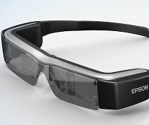 Epson Moverio BT-200
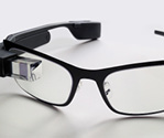 Google Glass
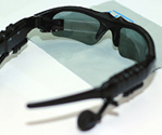 Lumus OE-32
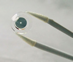 iOptik AR platform
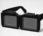 Pinlight display
 OST-HMD display
Freeform optics and field of view
Eyepiece optics also present challenges for designing OST-HMDs that look and feel like regular eyeglasses. The ideal eyepiece does not contribute excessive weight or bulk to the display, provides crisp images and a wide field of view (FOV). The AR displays highlighted in the table below have received tremendous enthusiasm for their potential to provide hands-free instant access to digital information. The Epson and Google products demonstrate exciting prospects of AR displays, but the designs have eyepieces based on rotationally symmetric technology, which offer poor scalability with FOV increases and can be relatively heavy.
Lumus Optical’s geometrical light-guide approach demonstrates good scalability with FOV increases, but it is subject to stray-light artifacts and high production costs. Additionally, it requires an infinite focus and thus is not compatible with a 3-D image source of finite focus. The contact lens approach may have the potential to achieve an AR display with a wide FOV, but the design requires the user to wear both contact lenses and eyeglasses, which is cumbersome. The recent pinlight technology demonstrated great promise for achieving a wide FOV in a very compact form, but it is limited by relatively low spatial resolution.
An alternative to these approaches, which we have been exploring in our own work, is to move away from rotationally symmetric optics and toward freeform, waveguide-like prisms, formed from multiple freeform optical surfaces. Such prisms have a waveguide-like geometry that guides light propagation from an image source, which might be hidden in the sidebands of an eyeglass-like display, or in the space above the eyebrow. Freeform optics have proved much more scalable, in terms of FOV, than rotationally symmetric technology, without significant impact on eyepiece thickness and weight. [See Optics & Photonics News, June 2012, p. 30.] And freeform optics eyepieces not only enable next-generation high-performance HMDs, but they also provide opportunities for improving existing HMD capabilities.
Freeform optics have other emerging advantages in the world of 3-D AR. For one, fabricating such surfaces at low cost is becoming practical, owing to advances in diamond turning and plastic-optics-molding technologies. And, more important, a freeform eyepiece is not particularly sensitive to the type of image source being used—which opens the prospect of combining this compact optical technology with the 3-D imaging possibilities of micro InI.
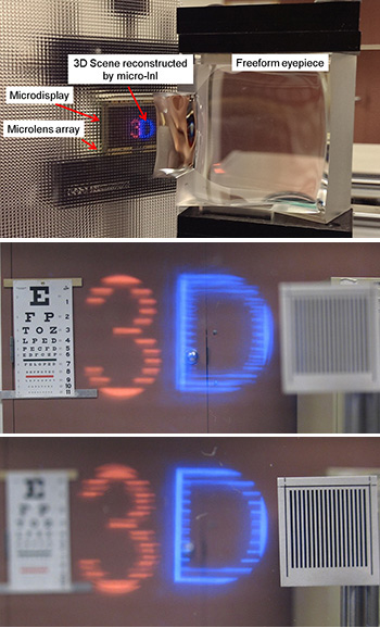 Monocular prototype of a micro-InI OST-HMD design: (Top) Experimental setup of the OST-HMD prototype demonstration. (Center) Reconstructed 3-D images demonstrate the effects of focusing the camera on the Snellen chart four meters away.(Bottom) Effects of focusing the camera on the grating target 30 centimeters away.
Proof-of-concept demonstration
The images on the left show a proof-of-concept monocular prototype of our micro-InI OST-HMD design. The microlens array has a 3.3-mm focal length and 0.985-mm pitch; the microdisplay is a 0.8-inch organic light-emitting display with 1,920 × 1,200 color pixels; and the freeform eyepiece has an equivalent focal length of 28 mm. The eyepiece combined with the micro-InI display unit yields a 33.4-degree FOV, a 6.5-mm exit pupil diameter and a 19-mm eye clearance.
We tested the prototype using a 3-D scene with the number “3” and letter “D” located about 4 meters and 30 centimeters away from the eye, respectively. Both objects subtend approximately the same visual angles to the eye. We used an array of 12 × 11 elemental images, each of which consisted of 102 × 102 color pixels. In the real-world view, we placed a Snellen letter chart and a printed black-and-white grating target about 4 meters and 30 centimeters away from the viewer, respectively. The number “3” appeared sharp when a digital camera was focused on the far Snellen chart, and the letter “D” appeared clear when the camera was focused on the grating target.
In addition to this prototype, Hua’s group has designed more than seven other lightweight freeform OST-HMDs for applications ranging from military to medical fields. When tested, these systems, with FOVs varying from 30 degrees to more than 80 degrees, maintained compact and thin profiles between 10 mm and 25 mm.
Although we observed light artifacts, our results demonstrate that the proof-of-concept AR display can produce correct focus cues and true 3-D viewing in a wide range of depths. Microdisplays with a larger number of pixels and smaller pixel size, as well as better quality lenslet arrays jointly optimized with the freeform optics eyepiece could substantially improve performance, as well as lateral and longitudinal resolutions. With these improvements, this design could eventually lead to a remedy for eye fatigue caused by convergence-accommodation cue conflict in OST-HMDs.
It is worth noting that the lateral and longitudinal resolutions of our current prototype are not only limited by the low pixel resolution of the elemental images due to micro-displays, but also by the limited depth of field of the freeform eyepiece. Optimizing the eyepiece for a stack of object-image conjugates could remedy this limitation. Furthermore, the design, fabrication and metrology of complex freeform optics, such as the wedge-shaped eyepiece, are more challenging and expensive than rotationally symmetric optics.
Future directions
While the concept of 3-D visual devices has been around since the 19th century, the widespread use of this technology has only recently accelerated. Likewise, OST-HMDs were first demonstrated in the 1960s, but compact, wearable systems have only recently become a potential commercial reality because of new developments in optics and optoelectronic devices. Moving toward an approach to 3-D that embodies integral imaging could benefit from breakthroughs in commercially available image detector arrays with small pixel size, from high-quality lenslet arrays, advances in microdisplays and computational imaging, and other advances.
The integration of freeform optics, optoelectronics, displays and information processing can be jointly designed to optimize image capture, AR and the displayed information, to create compact, lightweight, high-performance, visually comfortable systems.
Hong Hua is with the College of Optical Sciences, University of Arizona, USA. Bahram Javidi is with the department of electrical and computer engineering, University of Connecticut, USA.
References and Resources
-
G. Lippmann. J. Phys. 7, 821 (1908).
-
A. Stern and B. Javidi. Proc. IEEE J. 94, 591 (2006).
-
D.M. Hoffman et al. J. Vision 8, 1 (2008).
-
D. Cheng et al. Appl. Opt. 48, 2655 (2009).
-
R. Martinez-Cuenca et al. Proc. IEEE J. 97, 1067 (2009).
-
H. Mukawa et al. J. Soc. Inf. Display 19, 185 (2009).
-
H. Hua et al. Opt. Express 21, 30993 (2013).
-
X. Xiao et al. Appl. Opt. 52, 546 (2013).
-
H. Hua and B. Javidi. Opt. Express 22, 13484 (2014).
-
A. Maimone et al. ACM Trans. On Graphics 33, 1 (2014).
